Does a metal surface look similar to a rubberized one? Does a piece of glass reflect light the same way a piece of clear plastic does? No, right? (I sure hope you said NO!!). That is because of their different textures. Every object has an inherent texture and this makes it immediately identifiable. Nothing in the real world looks flat. This week’s article is quite exciting! It has helped me understand the steps needed, but often overlooked, to render objects as close to the real thing as possible. With a few example renders, I’d like to share what I’ve learnt. So let’s get on-to it then!
Adding texture to 3D objects is achieved through different types of maps. Why the name maps? Because they “map” the “texture image” onto the 3D surface and let the program know where to apply highlights, shadows, colors etc. I’d say that understanding the capability and function of each map is mandatory even before experimenting with them.
Lets briefly look at the different types of maps we can use: Color/diffused, Bump, Normal, Specular and Opacity maps.
I apologize for the watermarked renders. They were done on a demo version of Keyshot, but they do get the message through.
Color or Diffused map
This map is used to apply either a color, a pattern or an image onto the 3D model. Example: Applying a picture of wooden planks as a color map onto a 3D cube to model a crate. Once the required appearance has been applied, we can decide what the other maps have to do.
 The above image has black applied as a color map.


The above images show the applied rust pattern color mapped onto the sphere.
Now begins the interesting part – making it look realistic.
Bump map
This map lets the program know the “heights” or “bumps” on the surface. It is, in essence, a greyscale image where pure black (RGB 0,0,0) is the “trough”, pure white (RGB 255,255,255) is a “crest” and the shades of grey are all different heights above the surface (between the crest and trough). These images can be created in pixel editors like Adobe’s Photoshop.
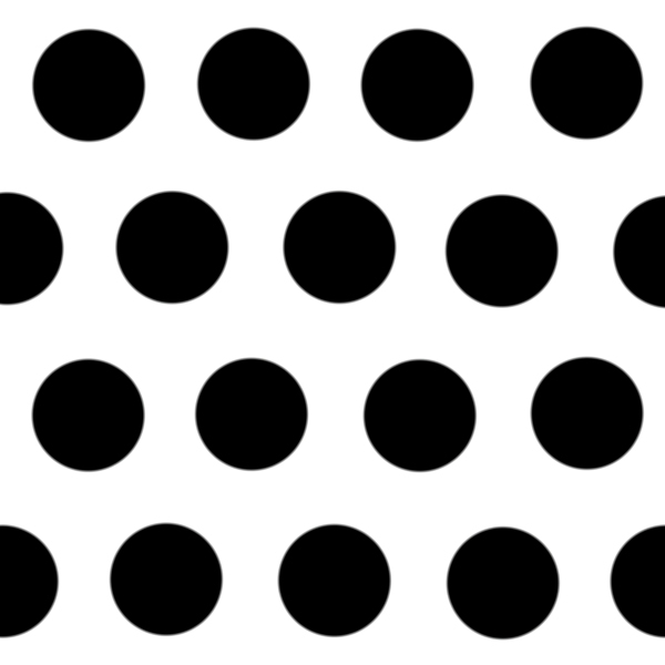

This BW image was scaled down and used to create the dimple texture.
The advantage of using this map is that it doesn’t add to the existing geometry and so, renders pretty quickly. But the results may not be a 100% accurate. Here, though the sphere appears to have dimples, a close look at the periphery shows us that the shape (curvature) remains unaffected. So, be aware of this map’s limitation.
Normal map
This is similar to bump maps in that they use images to define heights above the surface. The difference is that they are not greyscale images, but are RGB images mainly using violets and blues. They define the normality of the surface to the direction of the light. Normal maps are said to be more accurate than bump maps, but I think for my application, bump maps are enough. They are easier to create too.

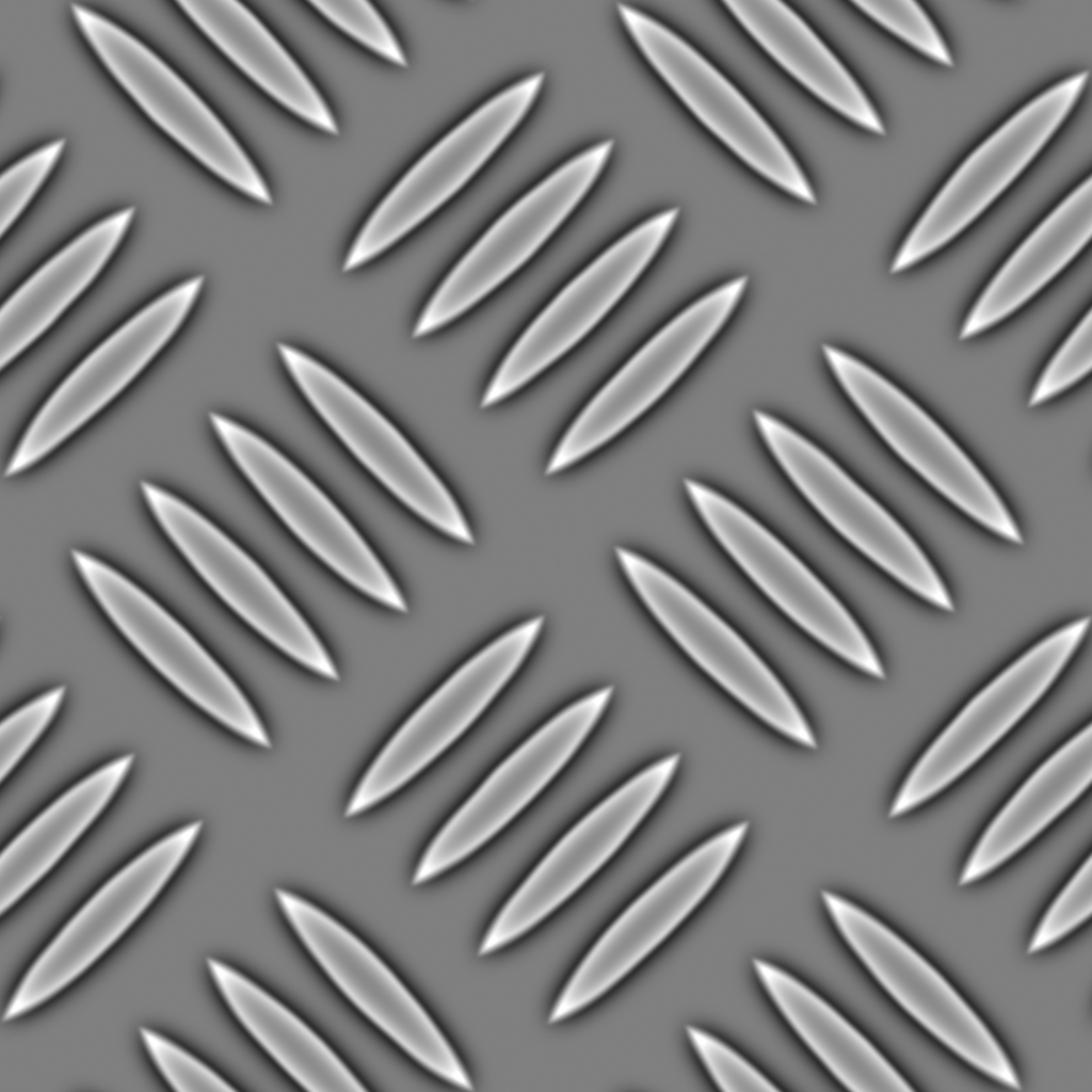
This is an example image for a Normal map.
Displacement map
Displacement map option is not present in Keyshot at present. It works similar to a bump and normal map and so is good to know about.
It gives the most accurate results, but is also the most resource intensive. Where displacement maps differ is that they affect the model geometry; they modify the surface to provide the required texture. In the bump map example, the sphere appears to have dimples, but the actual surface remains unchanged. But if it was a displacement map, there would be actual dimples created on the surface. Now, if we look at the periphery, we would see an uneven surface instead of a smooth one.
Specular map
This is the map which specifies areas to be highlighted. It is also a greyscale image where white is brightest highlight, black is no highlight and greys are different levels of highlights. This, in combination with either a bump, normal or a displacement map gives near realistic renders.
Greyscale image and sphere model selected for this map.
 Specular map applied. Only areas highlighted are those where the greyscale image has whites and greys. Note the absence of highlights on the edges.

The same image applied as a bump map, shows indentations on the surface. Highlights are visible on the edges as well.

Same greyscale image applied as both bump and specular map. This looks more realistic than applying only a bump or a specular map. Note the controlled highlights in this render.
Opacity map
This is a very useful map and you will see how. Just imagine the pain of creating holes in a symmetric pattern on a sphere. It takes a considerable amount of planning and steps to pull this off in CAD programs. But, in the rendering stage, we can use an opacity map to “create” holes or transparencies on the surface, which do not actually exist in the model.
This map also used a greyscale image, where areas mapped black are completely transparent, and white means opaque. Greys are different levels of transparencies. Now, with an image with black holes on a white background can be used to “create” holes on a surface. Its as easy as that!
Greyscale image and sphere model selected for this example.

Holes created using only an opacity map.
Another example : this map can also be used to create an illusion of a glass model (without even applying a glass material!)
A combination of all these maps gives a pretty convincing render:


This must give you an idea on what each map does and how to use them to get the desired results. Some prior planning and decision making is necessary to help select/make the required images to be used for each map. Though all the maps don’t have to be used for every render, a combination does give better results most of the time.
Moving forward, do use what you read here as a reference and practice rendering basic shapes like spheres, cubes, cylinders and cones with different maps and images. This will help develop a deeper understanding and will make the texturing process faster, easier and more intuitive.
If you have any questions about these maps or think something is not accurate, drop a comment or an email. I’d love to discuss about it!
Until then, cheers!
